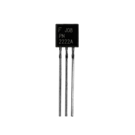

When the transistor is turned on, current flows from the source to the ground through the load.The low-side switching of a load requiring a higher voltage (than \$V_\$. The load (in this case, an LED) is linked to the switching output with a reference point in this type of switching connection. When no or zero voltage is applied to the input, the transistor works in the cutoff region and acts as an open circuit. As a result, the transistor acts as a short circuit. The Plan is to use only 3 switches for these 5 operations this is gonna be realized with an arduino nano with holding the buttons for different durations. The Module i chose has 5 switching options for Play/Pause Next/Prev Volume-Up-Volume-Down.
Pn2222 transistor threshold upgrade#
The collector to emitter voltage is almost equal to 0 when a sufficient voltage (VIN > 0.7 V) is applied between the base and emitter. Hi there, i am currently trying to upgrade my car HiFi System with a CSR8645 Bluetooth module. A transistor's switching operation is based on the voltage applied at the base terminal. The switch is turned off when there is no base voltage.
Pn2222 transistor threshold how to#
That puts a (good) transistor well into saturation when MCU output is near 3.3v. At high collector to emitter voltages the current limit decreases due to the voltage across R21 from D3, D4 and R20. Ive been continuing to play with small circuits and Im trying to sort out how to calculate the resistor for the base of this transistor. The transistors are both 2N2222, which are BJT NPN transistors. So we use 2 transistors in this circuit for operation.

In other words, when a voltage is supplied to the base, a transistor conducts current across the collector-emitter. Assuming the 2N2222 is good, and the MCU gnd the emitter voltage, and assuming the MCU output goes to 0.0 volts, that circuit should work. The astable multivibrator circuit we will build with transistors is shown below. One of the most common uses for transistors in an electronic circuit is simple switches.

The emitter-base and collector-base junctions are forward biased in this region. Switching and digital logic circuits are primarily used in the Cutoff Region. In this mode, the BJT is switched off and the circuit is an open circuit. There is no current flow except small leakage currents because both PN Junctions are reverse biased (usually in the order of a few nanoamps or pico amps). The collector-base junction and the emitter-base junction are reverse biased in this mode. Current flows between the emitter and the collector in this mode, with the amount of current flow proportional to the base current. Two junctions are biased differently in active mode, with the emitter-base junction being forward biased and the collector-base junction being reverse biased.

The transistor is generally used as a current amplifier in this mode.


 0 kommentar(er)
